Introduction
At the time of this writing, I could get the 2000-watt Dataouboss inverter for a little over 100 bucks. Is it possible to find a good inverter for that price? Maybe! This post documents an exhaustive and thorough test of the Datouboss SAK 2000w 12v Off Grid inverter which entered the US/NA market recently. I love solar power equipment – especially building and using Direct-PV-DC power systems. Although I have a desire to simplify and streamline solar power and reduce dependency on complex electronics, I still love DC-AC inverters. Nothing gets me curious like putting a brand new off grid power inverter to work – to “see what it can (or can’t) do”…
Welcome to a new series of articles on this blog. They will focus on teardown and in-depth engineering analysis of specific equipment. Typically, most of my articles have a a companion video – but these will emphasize a blogging format. Enjoy! -Dave, SPE
Meeting A Brand New Inverter: Learning Its Name – And Taking It Apart
In this first article of a series, we start with a quick look at the exterior features, then open the inverter’s case to see what’s inside. I will give an overview of the internal components and then we’ll move on to an exhaustive and lengthy real-world test. Note: MFUZOP is a sub-brand of Datouboss! This sample carries that name.
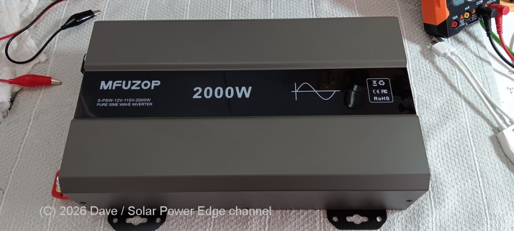
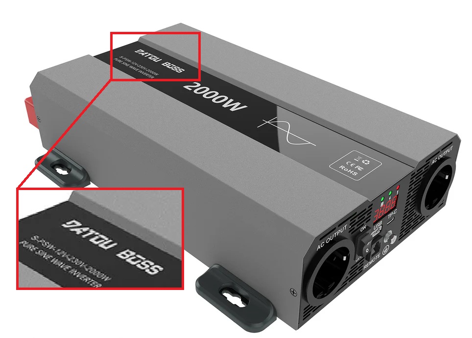
First off, this inverter is intended as a budget concious option, so I will consider that during the test. Taking a quick look at the inverter’s external appearance, we can see the outer case uses a stamped steel design. I think this type of construction has a higher quality feel than the typical extruded aluminum clam shell design, but that is my personal opinion. Subjectively, the inverter seems slim and compact for it’s rated power output.
Compared to a low-frequency inverter, this high-frequency design is very lightweight and easy to move around. It has steel mounting ears for attaching the inverter to a wall or surface, or the included nonslip rubber feet can be attached instead.
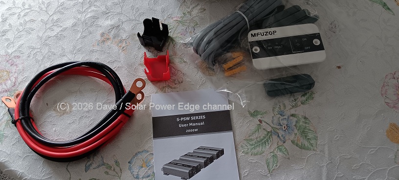
Included Accessories
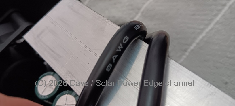
A remote On/Off switch is included along with a set of doubled up 8awg high strand count silicone cables. I had to use my own longer and thicker copper stranded cables for this test as I usually do. Considering the price point, it’s nice to see a set of included cables for those who don’t already have a set.

Frequency Mode Switch
An unusual feature is the 50/60Hz mode switch right on the front panel of the inverter. One would need to be careful not to accidentally move this switch after setting the correct frequency.
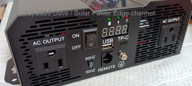
USB Outputs
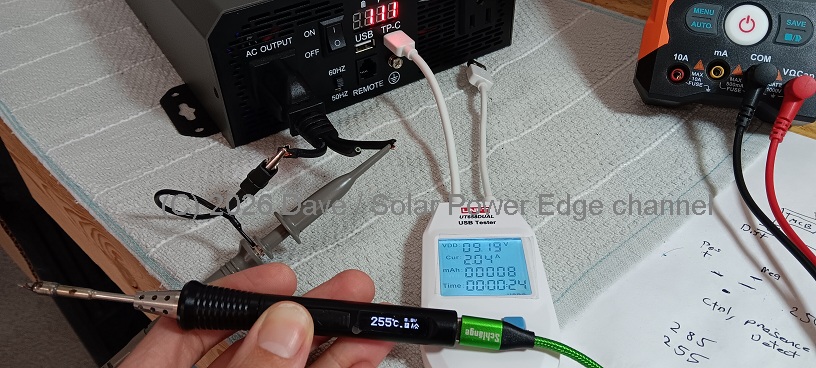
In the interest of being thorough, I tested the USB ports on the front. Most people don’t buy inverters for USB outputs, yet it’s common to find these ports as a value-add on many DC-AC inverters today. They can be quite handy at times. The USB-C output had no problem running my USB soldering iron, outputting 9.19 volts at about 2.04 amps.
There are 2 American style AC 120v Outlets on the front. I assume the European version is 230v/50Hz but this US-market sample is 120v/60Hz or 50Hz if you flip the switch on the front.
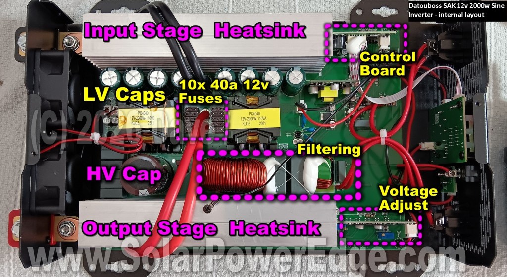
Inside the Datauboss SAK Inverter – Teardown & Analysis
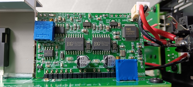
The outer case of the inverter comes off as one stamped metal piece – with several screws holding it on. Inside is a surprisingly rather clean looking PCB! It has several daughter boards and the cable management looks OK at first glance. More on that later.
Items of note:
There are 2 precision trim pots on the board, one is marked VR1 and this is used for adjusting the output voltage. Out of the box, the inverter output approximately 110vac and did not need any adjustment.
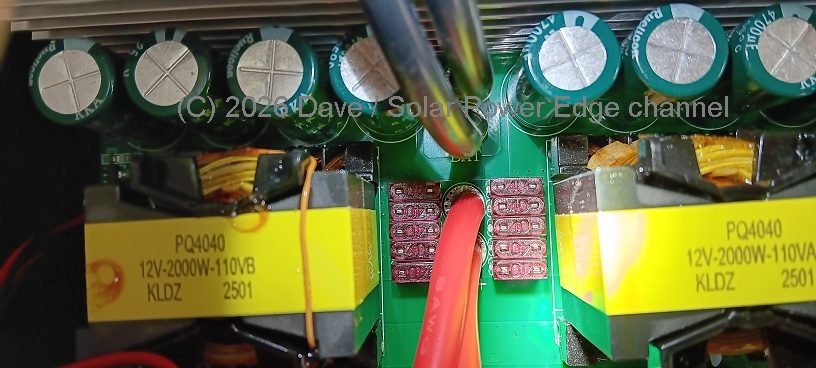
Input capacitance on the low voltage side (12 volts input) consists of 8 pieces of 25v 4700uf capacitors of an unknown brand. High voltage DC (Boost) stage has a single large 315v 1000uf capacitor.
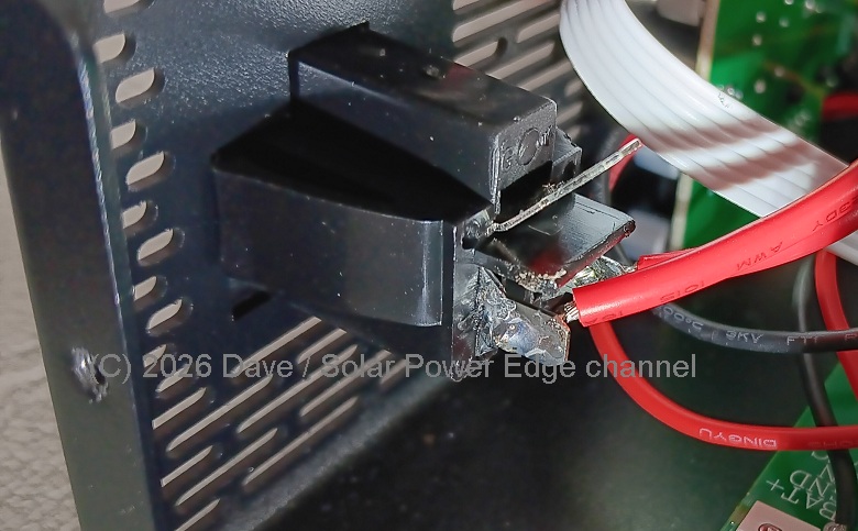
The wires feeding both AC outlets are soldered on. I do this all the time so it doesn’t bother me. But it would be nice to see some heat shrink or other protection on those connections in case one gets hot and melts the solder. To be clear lead-free solder melts at over 200C (392F). If those AC output wires ever did get that hot, let’s just say there’s a serious problem somewhere…
Note that the ground pin of the AC outlets is floating, meaning it’s not attached to anything. In some installation scenarios, I might open an off the shelf inverter and tie the 3rd pins into an available earth/ground connection – after testing for a live neutral configuration of course. But there’s no reason to do that here, anyway modifying the inverter is not compatible with an out-of-the-box test.
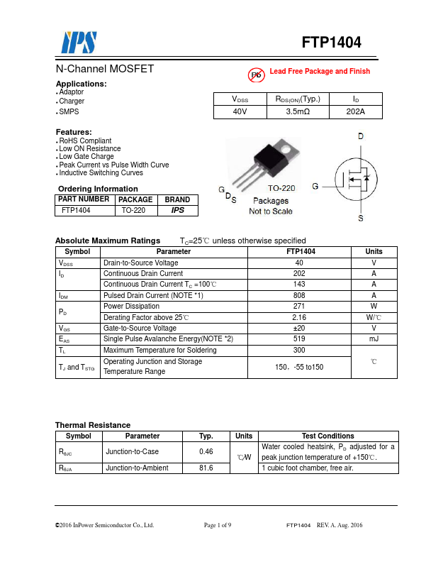
On the low-voltage (12 volts) input side of the inverter, we find a lot of MOSFETs part # FTP1404. These handle the “chopping up” of the low voltage to low-voltage AC. They are securely clamped to the heat sink, and none of the clamps appeared bent or distorted. The FTP1404 part itself is rated at over 100 amps continuous, with proper cooling of course.
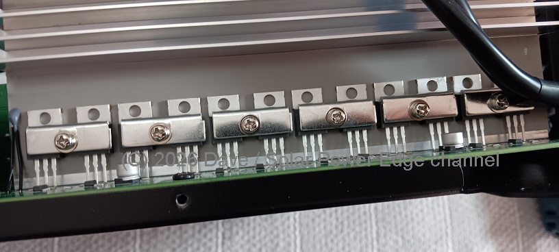
It’s necessary to remove the clamps from the low voltage MosFETs to see the part number:
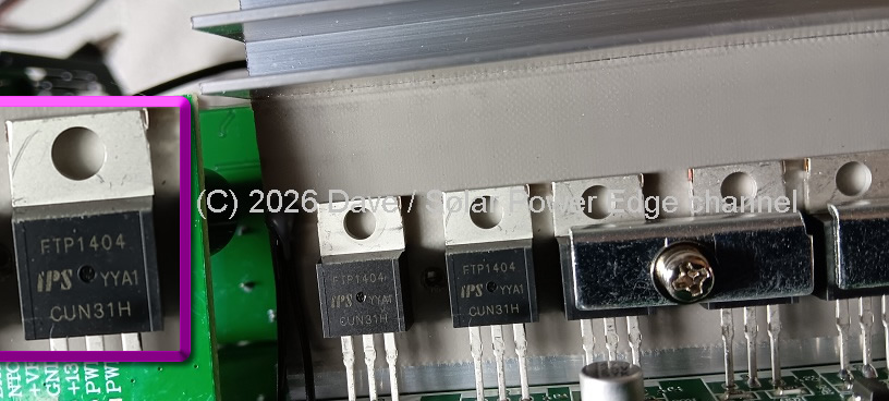
The low voltage AC is fed fed into a pair of transformers to create high-voltage AC.
This is then rectified to high voltage DC. It is the high voltage DC which is used to create the final modulated AC sine wave output.
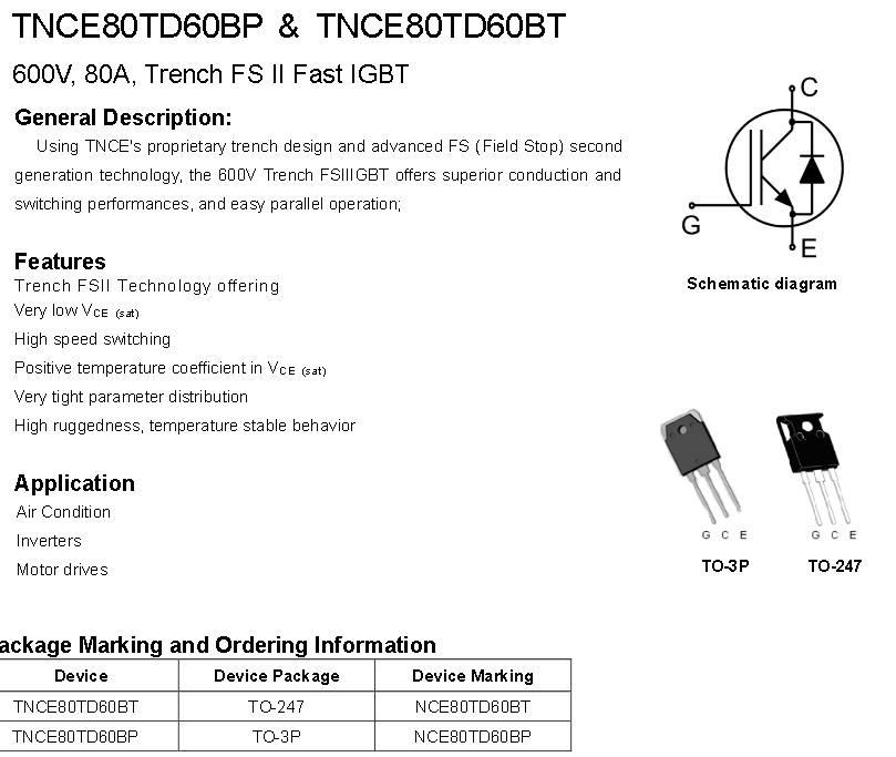
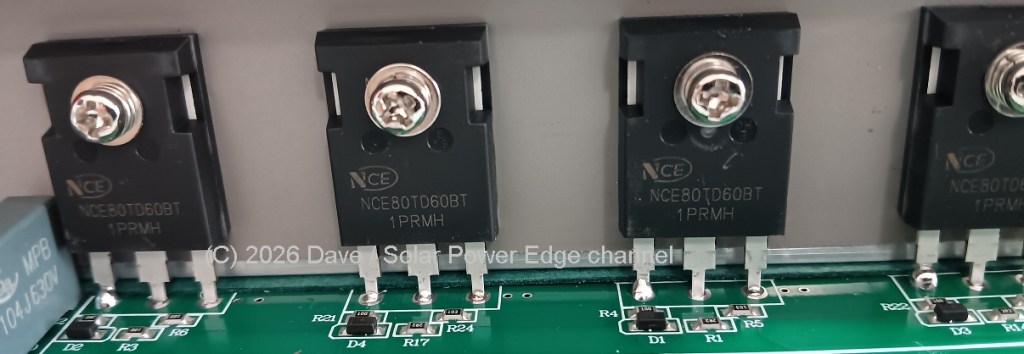
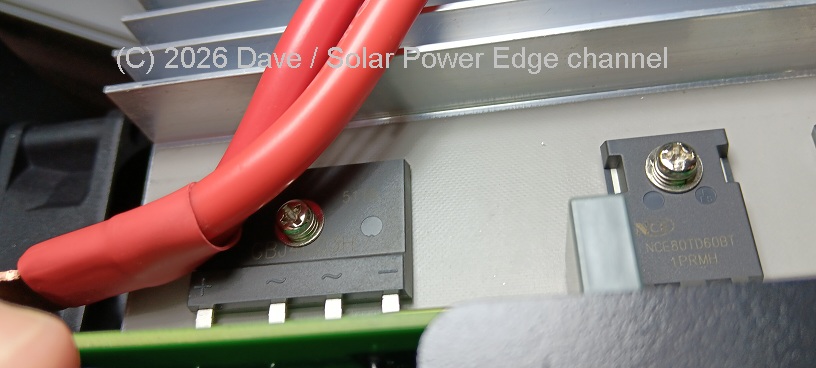
The high voltage (AC output) stage has 4 very beefy looking IGBTs part # NCE80TD60BT rated for 80 Amps.
Since this inverter is supposed to handle 2kW of AC output, I would expect rather thick cabling inside and beefy terminals. In reality, it’s not a good idea to run a 2000 Watt inverter at it’s max rated capacity for very long. The reality of solar is that most equipment is constructed in a cost conscious manner, and may not be able to handle long term heavy usage. Thinking this through – under normal operating conditions, I feel it’s reasonable to continually push 50% of the nameplate power rating through a commercial off the shelf inverter.

While keeping this in mind, I think the short runs of low voltage input wiring inside are adequate. They consist of 2 runs of doubled-up 8 AWG (approximately equivalent to 6awg) high strand count silicone jacketed wire. The wires are wrapped over the aluminium heat sinks. While the wire is high quality and the heat sinks are not sharp, the wires would benefit from woven wire wrap where they contact the heatsinks.
Cable Management
Cable management is always a challenge in inverters. My main concern is protecting wires from rubbing through and creating a short circuit. At least there are zip ties where appropriate, and nothing inside looks like it would move out of place over time.
The internal connection to the battery terminal posts were very tightly torqued as they should be. They look adequate to support at least 1000w continuous power draw.
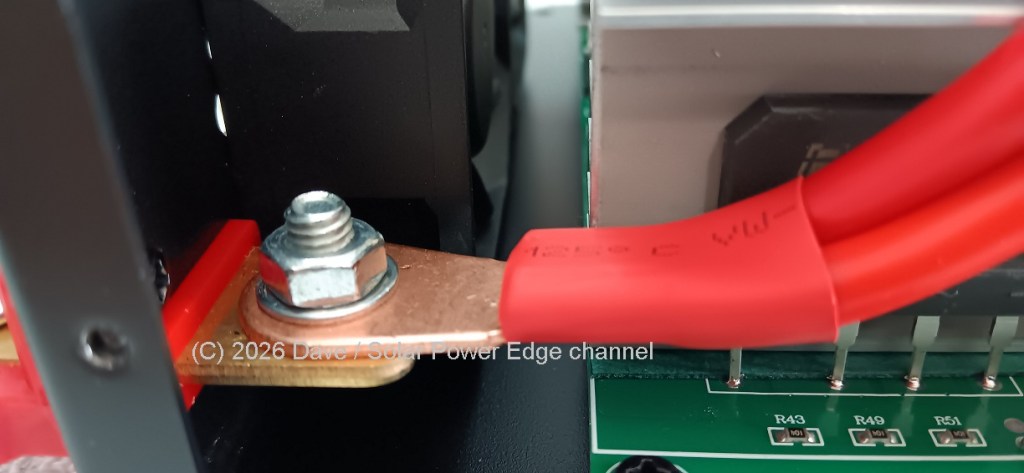
The 12-Volt input terminals (studs) themselves have M10 threads and look suitable enough for the job.
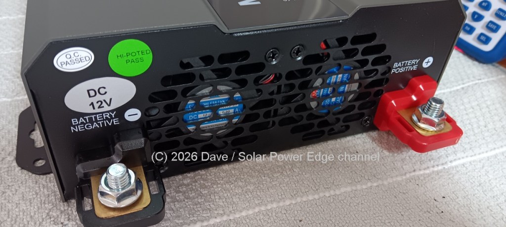
From the outside, the inverter certainly looks like it could handle 100-200 amps at 12 volts – but that is a first-glance educated guess before testing takes place.
Fuse Protection
When installing a 12v 2kW inverter, it’s entirely imperative to use a DC fuse inline with the power cables feeding the inverter. Nevertheless, it is very common to find soldered or socketed fuses on the mainboards of many inverters. These act as a “last line of defense” in the case of catastrophic failures.
This inverter is not an exception; inside, we find no less than quantity 10 of 40-Amps 12v DC mini fuses soldered to the mainboard in parallel – for a total of 400 amps. This is good to see, as it (hopefully) indicates the designer is confident the inverter can take the 200~ amps or so at 12 volts needed to output 2kW of AC power.
Thoughts So Far
I spent considerable time examining the inside of this unusually clean inverter design. I could not find any major fault or flaw. Because of that, I am hoping it performs well in my tests.
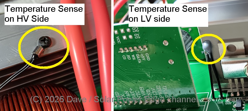
Temperature Sensing
Both the low voltage and high voltage side heat sinks have a thermistor or temperature sensor attached, which is nice to see. And that dovetails smoothly into the next phase of this teardown – real world testing!
Next: Putting The Inverter To Work
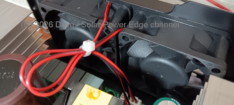
Cooling Fans
I hear this question all the time – “Are the Fans Loud??” It seems like a cliche but then again who wants to listen to fan noise. The fans on this inverter are pretty loud. The good news is they don’t stay on all the time – and are temperature controlled.
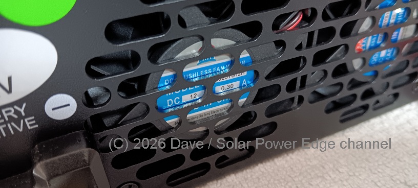
All power equipment must have cooling, and often it doesn’t even have enough for long term durability. So while I don’t want to hear fans, I understand they must exist to avoid the cost and weight of a massive and expensive heat sink and to reduce the risk of overheating.
My personal preference is for fans to come on low all the time at a certain load threshold. This prevents on/off thermal cycling. In past projects, I modified inverters and charge controllers with quiet boost fans that are independently powered and which improve cooling performance with very little noise. Perhaps I will do the same modification to this inverter after the testing is complete.
| Related Content: DIY Cooling Fan Upgrades | ||
 |  |  |
My 24×7 Inverter Test Setup
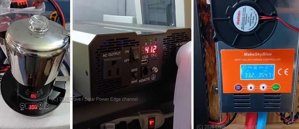
I decided to start the test in the utility room of my house. We just moved in and are starting to install solar equipment to power our circuits off the electrical grid. The inverter was connected to ~1000 Amp-Hours of Lithium Iron Phosphate (LiFePO4) 12v batteries through a 250 amp ANL DC fuse.
The batteries are fed by 800 watts of solar panels outside and currently a 60-amp MakeSkyBlue MPPT charge controller. This is a small setup but very reasonable for a variety of common scenarios.
The inverter’s first task will be to run 2 chest freezers 24×7 along with an assortment of other resistive and inductive loads both large and small. This test will not be short term and will continue non-stop. Hopefully, the inverter survives!
Inverter Efficiency and Idle Power Draw
Efficiency is a broad term. Electrical efficiency in particular is a major concern when evaluating an inverter. This inverter is a traditional electronic high-frequency design and thus it’s “electrical” efficiency is better than most or all low-frequency (LF) design inverters. We will calculate the overall electrical efficiency of this inverter later under various realistic testing scenarios.
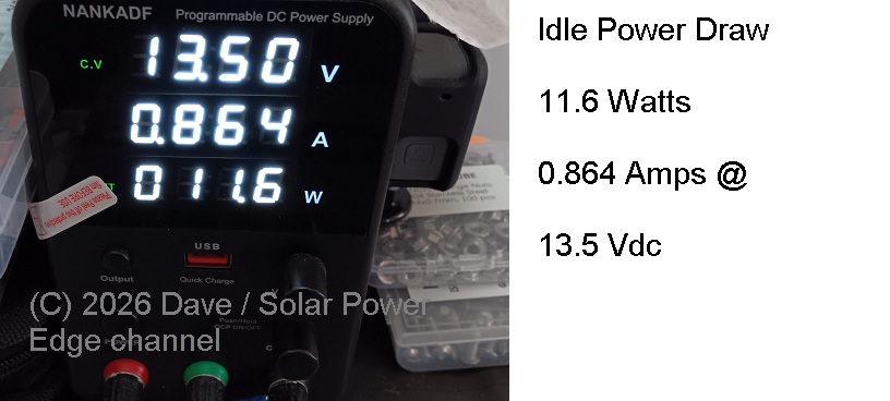
In a smaller off electrical grid solar power system, the idle power draw (meaning the inverter is in standby, outputting AC voltage but powering no loads) is very important. Even if we aren’t powering any loads, the inverter will have to consume a certain amount of power continuously in its standby state. With a smaller battery, that power loss can add up really quite fast. In many cases a lightly loaded inverter will have worse electrical efficiency than when running heavier loads. In a larger system with more batteries and energy storage, the idle power draw isn’t quite as much of a concern.
This inverter consumes about 11.6 Watts when it is powered up but no loads are attached. That’s not exactly terrible. Probably about average for this type of unit. We would lose about 0.28kW/h of energy or (280 Watt-Hours) per 24-hour day just for the privilege of having the inverter online and ready to power loads.
What Does “Real-World Testing” Mean To Me
It has more than one meaning. I love testing solar power equipment in real-world conditions over the long term to check long-term durability. But when doing a test for public benefit, it often makes sense to push equipment a harder than what is truly reasonable or normal – in order to expose any potential hidden flaws that might impact normal real-world use cases.
You can see an example of this in my recent review of a 3500w 12v inverter, where I pushed it beyond what I thought was reasonable. However, this gave me confidence the inverter was durable enough and should survive more reasonable long-term use cases.
In real-world conditions, I operate my inverters at no more than 50-80% their rated capacity – with proper cooling. This is for longevity and to protect my investment over the long term. If operating conditions are harsh, such as outdoors or in hot summer temperatures, I may down-rate the standard to no more than 50%. So using my own standards, for a 2kW inverter, I’d normally operate at 1kW-1.6kW (1000-1600 Watts).
Why Real World Testing Alone Isn’t Enough
There is a reason why the UL (Underwriters Laboratory) exists. They push equipment beyond what is reasonable and deliberately into failure. That is one of the primary methods to expose strengths and weaknesses of a specific piece of equipment.
So that’s why I tend to push inverters harder in the initial testing. If it survives, there is a bit of extra hope that it’s probably going to last a pretty long time – under more reasonable conditions.
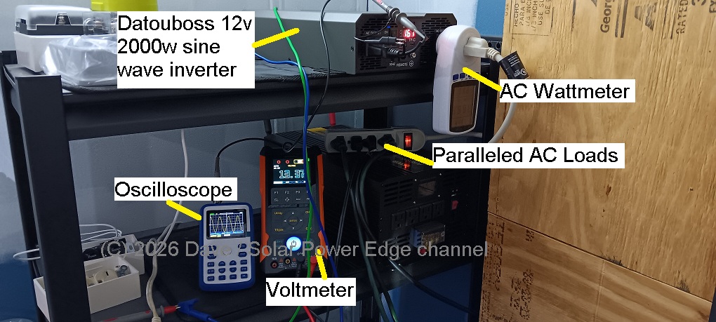
The Initial Test Setup
While I’m not as well equipped as the Underwriters Laboratory, I have set up the following test environment for the Datouboss inverter:
- Power Source: 1000 Amp-Hour Lithium-Iron-Phosphate (LiFePO4) 4S 12 volt batteries in parallel
- Power Connection: 0awg copper stranded cable 7ft
- Fuse: 250 Amp DC ANL fuse
- Rated Load stress test verification
- Standard load test: 1000 Watts (DC net input) continuous for 1 hour
- Extended mixed load test: 100-800 Watts (DC net input) continuous
- Compressor Start Test: 2 chest freezers – simultaneous start / Dehumidifier
- Loaded Wave Form Distortion Test – resistive load (heater) + surge (compressor)
- Cooling/Fan test: internal temperatures
A Mix of Loads
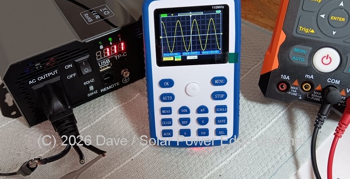
In many electrical grid independent solar power systems, it is common to have a mix of loads on a single AC power switch. Thus when suddenly switched on, they can present a considerable challenge to the Output stage of a HF inverter. It is very difficult for the MOSFETS/IGBTs and onboard computer to maintain a perfect sinusoidal waveform during the brief surge that takes place at switch-on. Typically, I like to capture this surge on an oscilloscope to see how the waveform looks under such conditions (see below).
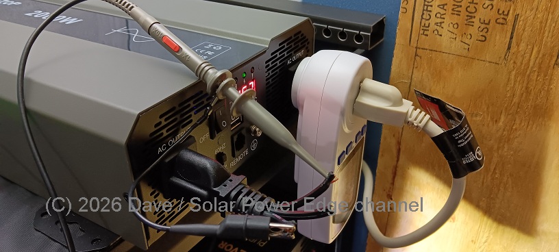
Oscilloscope Connected to a Chopped Off Power Cord: Don’t Do This At Home!
Test #1 – Surge – Light Mix of Inductive + Resistive Loads
For the very first test of the Datouboss SAK inverter, the main goal is to confirm it works properly before plugging in bigger appliances. I connected a single power strip to the inverter and plugged in 1) a small resistance space heater of about 250w and 2) an electric AC box fan set on low and 3) a couple of chest freezers including a 5 cubic foot and a 3.5 cubic foot. I switched all loads on simultaneously to challenge the inverter’s output electronics.
Note that in this test, the compressors on both freezers engaged simultaneously along with the space heater and box fan.
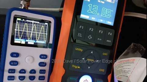
Below you can see a picture of the brief harmonic distortion which occurred on the waveform during the first moment of the surge test:
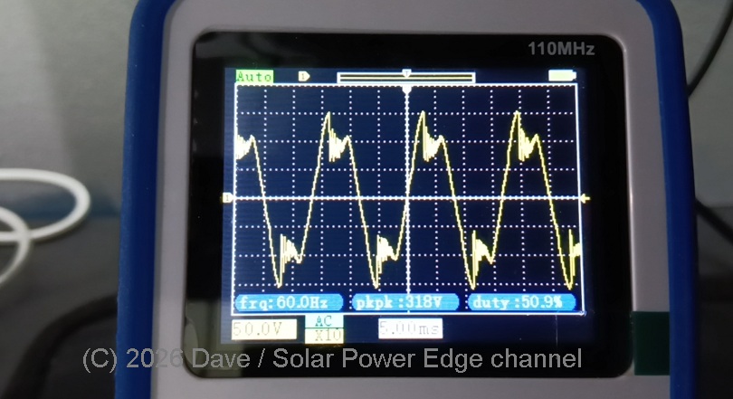
For just a short time, the output does not resemble a sinusoidal waveform at all. In fact it looks more like a triangle wave. But this is very common with HF inverters I have tested. Since I’m used to seeing it and it only occurs for a very short time (miliseconds), it’s not a major concern here. The above image plainly shows the reality of switched electronics and high-frequency inverter designs. It’s hard to keep a perfect sine wave going by switching MOSFETs when a surge takes place.
I don’t think the brief distortion is harmful to say, a chest freezer, or generic commercial off the shelf appliance utilizing a switch-mode power supply (SMPS). If the equipment being powered was highly sensitive, this distortion could cause interference, noise or damages; but then again, we’d probably use a separate inverter for such extremely sensitive loads anyway.
Test #1 – Lightly Loaded – Calculated Electrical Efficiency @ 168w
I forgot to keep the heater switched on during this measurement, so only 5cf and 3.5cf chest freezers were operating. Doesn’t invalidate the test as only a light load was required. The loads were allowed to stabilize and the inverter’s overall electrical efficiency was as measured follows:
| Input (DC) | Output (AC) | Efficiency |
| 13.38 Vdc | 111 Vac | – |
| 14.75 Amps | 1.52 Amps | – |
| 197.36 Watts | 168.8 Watts | 85.5 % |
So under a light load (about 8.4% of rated capacity in this case), we have an efficiency of approximately 85.5%. Typically, inverters are less efficient under light loads. So we will see if that number improves under heavier loads.
Test #2 – 50% Loaded – Calculated Electrical Efficiency @ 1,028w
The next test took place with 2 space heaters and a 5cf freezer.
| Input (DC) | Output (AC) | Efficiency |
| 12.91 Vdc | 111.2 Vac | – |
| 91.20 Amps | 9.297 Amps | – |
| 1,177.392 Watts | 1,028.0 Watts | 87.3 % |
Under a load of 1,028 Watts (51.4% of rated capacity), efficiency does indeed look better. It improves by 2.1% to 87.3% which is definitely outside the margin of error.
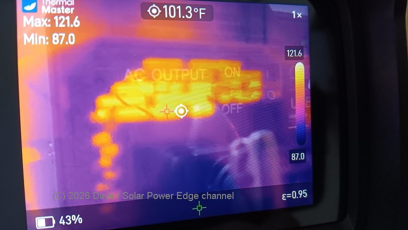
The inverters LED display alternates between battery voltage, AC voltage and wattage. In this picture it shows 1,031 AC watts, very close to the measured 1,028.
In this test, the inverter generated significantly more heat and the fans came on constantly. The outside case of the inverter was noticeably warm, about 90F (32.2C) while the hotter internal components of the inverter started at around 121.6F (49.8C) and some were over 131F (55C).
I switched on one of the space heaters while it was under load from yet another smaller space heater plus a freezer, reaching a power level of over 1kW. In this case, there was no noticeable distortion of the sine wave output.
Test #3 – Voltage Regulation – Washer Cycle (Induction Motor)
Our washing machine has a “gentle” cycle that pulses the motor constantly. Since the motor is an induction load, it definitely can challenge the output to maintain a clean sine wave, as well as test voltage regulation performance.
When running the washer in this cycle, the waveform remained a clean sinusoidal shape, so no problem there. With each pulse of the motor, the AC voltage dropped randomly, enough that it was noticeable – but certainly not enough to be harmful. Below is an animated GIF showing one example of the variation:
Test #4 (24×7 Off Grid endurance) Mixed Loads 50-500w Continuous
Further testing took place over the weeks leading up to the publishing of this article.
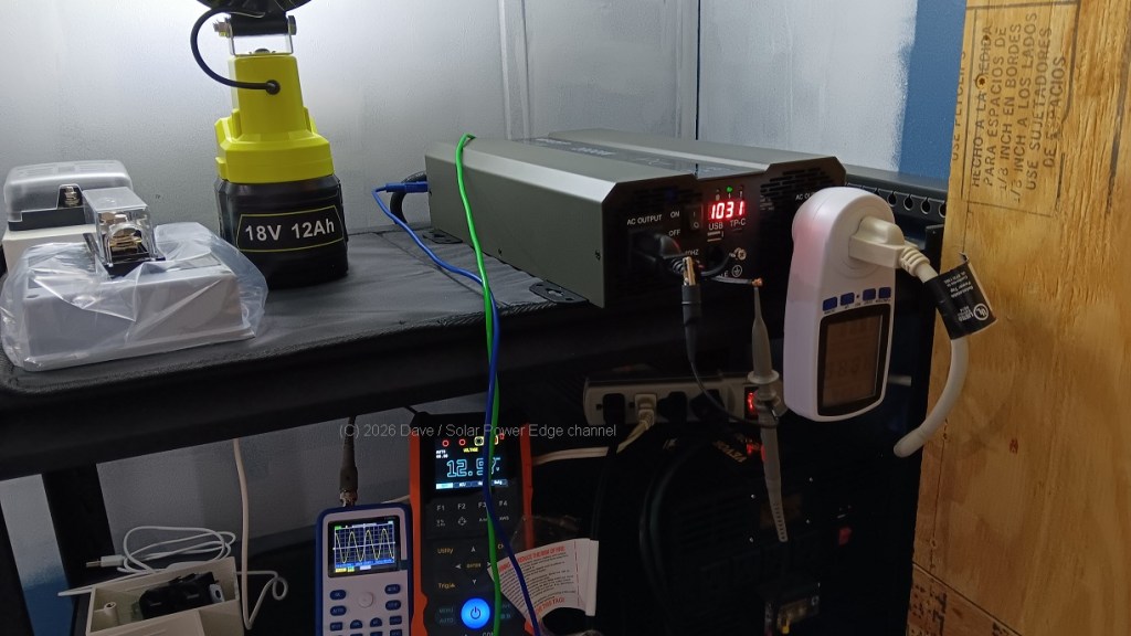
The following loads were powered: compressor based dehumidifier, induction cooktop, 2 chest freezers, 2 space heaters, an LED lamp, washing machine, box fan, USB charging, Ryobi 18v power tool battery charging. At no time was the inverter powered off.
The dehumidifier itself provided a continuous induction load hour after hour, while also running 2 freezers. Total wattage was 400-450w.
During continuous operation, the inverter’s fans cycle on and off quite often. I would not complain. Fan noise is expected and helps prevent internal components from heat soaking and experiencing premature failure. Thankfully I don’t even hear the fans most of the time as the noise is confined to the utility room and adjoining kitchen area. As the sun was shining in these weeks of the test, I had plenty of solar and was able to push the inverter continuously.
Extended Testing, Final Thoughts and Summary
As of this writing, the Datouboss SAK 2000w inverter continues to power our loads 24×7 without a hiccup. Usually during these tests I tend to expect some kind of mishap – but so far, so good.
Test Update 3-17-2026 This inverter is still powering a mix of loads 24×7 in non-stop operation. It has not shown a single issue or hicuup at this time. Loads run: compressor-based dehumdifier, induction cooking, 2 freezers, box fan, battery chargers, lighting.
Final thoughts and summary on this inverter. What stands out to me most is how actually good some high-frequency budget friendly inverters can be. I have used and tested a lot of inverters – mostly standard off the shelf budget models as opposed to high-end expensive boutique brands. There are so many different options it can seem overwhelming to make a good choice. While keeping price in mind, primarily what I look for in an off grid inverter is build quality and intelligent design. Bonus points if the equipment last more than 3 years. Examining build quality requires opening the inverter. When I did that here, I liked what I saw. Again keeping in mind this is a low cost inverter. Anyone can nit pick at electronics, but what I’m looking for is major flaws. So far I haven’t found any.
Beyond the Datouboss’s budget-friendly price, I like the clean no-nonsense design. There aren’t many bells and whistles, instead the focus is on the primary task – making AC power. The sine wave looks good under most loads. Based on its performance, I believe it’s able to handle 500 watts continuous 24x7x365 and burst to 1000 watts with proper cooling (so inside an air conditioned building for example).
For someone who is just starting out in solar – maybe getting some of their loads off the electrical grid, or even reducing their power bill, I think this Datouboss 2000w is a good option. For those who have been in solar a long time (such as myself) sometimes we want a backup inverter or separate inverter to power loads like freezers – and again the Datouboss 2000w is a good option. And since I cannot afford to buy high end solar equipment, I fully appreciate having access to models like this.
I have really enjoyed using this inverter and plan to keep it in production full time. With this inverter, we are already on the way to moving more AC loads off the electrical grid. Now if only I had a life like these folks, I’d be all set:
Where To Buy (NO Affiliate Sales Commissions)
Since I rather liked this Dataouboss SAK 2000w inverter I have no problem recommending it. I think it’s a good budget option for those with reasonable expectations. Here are links to purchase it if you are interested.
If you have any questions or feedback to share about this inverter, feel free to email me on the contact page.
No affiliate sales commissions are accepted for these links. I am posting them here for your convenience!
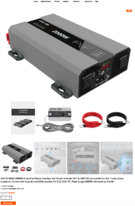
Dataouboss 2000W 12V Inverter Purchase Link:
You can use this code for an extra 8% OFF!! Again I don’t collect any commissions. SPE8
Entire Datouboss Inverter Collection:
Datouboss Pure Sine Wave Inverter Collection – In Stock
Datouboss LiFePO4 Battery Collection:
Dataouboss Lithium Batteries LiFePO4 12v 24v 48v Web Store
Dataouboss Canada (Only batteries, inverters are on the way)
Dataouboss LiFePO4 Batteries – Canada
I hope you enjoyed this close look at a new inverter product on the market. Thanks for reading and see you next time! -Dave, SPE
